NKI (B. V. Nederlandse Kleurstofindustrie, a subsidiary of Morton-Thiokol, Inc. U.S .A.), and one of the major industrial firms in the Netherlands, had a problem with extremely toxic TDI (toluene di-isocyanate) emissions from one of their processes .
On a batch basis in different reactors, the largest being 6.5 m cubed(1717 U.S . gallons), a solution polymerization of TDI with polyols in a solvent mixture is carried out. Control of the reaction is accomplished through the use of external heating or cooling. The reaction is exothermic and, if control breaks down, an extremely dangerous runaway condition could occur. To prevent overpressurization and/or overheating of the system during an upset, a safety-relief system has been installed . A safety-relief valve is set to relieve the runaway reactor at 3.923 x 10 to the fifth Pa gauge (56.9 psi g) which would correspond to a 160°C (320°F) temperature for the solvent mixture. In contrast, the reaction is designed to take place at 9.81 x 10⁴ Pa gauge (14.23 psig) and 80°C (l76°F).
The vent lines from the reactors to the scrubber system are sized to handle the most severe upset condition. The jet-Venturi design allows for very little resistance to flows substantially greater than the maximum rates anticipated. In addition, although only gases would be released by the relief valve, the jet-Venturi design can handle two-phase flow without hindering performance significantly.
The emergency condition noted above hopefully will never occur. The emissions resulting from this emergency must, however, be able to be handled so as not to endanger the health of the plant workers or the plant’s neighbors.
In addition, a continuous TDI emission problem of a much smaller magnitude exists. During normal plant operations, a small amount of toxic vapors are vented from the reactors. Combined with this flow are the vapors carried away from an adjacent drum-filling station by an exhaust fan. In both cases TDI is the toxic component which must be removed.
NKI came to the CR Clean Air Group, LLC through its representative in the Netherlands, Petrarca B. V., for a solution to their two-fold air-pollution problem. The manufacturer, working in conjunction with engineers at NKI and Mr. Alloys Petrarca of Petrarca B. V., were able to offer a scrubbing-system design and, ultimately, the equipment to handle the hazardous emissions, both chronic and potential.
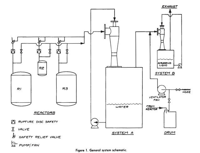
In basic form the air-pollution control system consists of two Venturi fume scrubbers operated in series, each installed on top of its own separator/liquid storage tank. The first stage, system “A”, operates only if the polymerization reaction runs away and relief from the reactor, or reactors, is required. System “A” is larger by more than an order of magnitude when compared- to system “B”.
System “B” is continuously in operation. It handles the remaining gased discharged from system “A” during emergency conditions, and the normal vent gases passing through an inactivated system “A” continuously as well as during emergencies. (See Figure 1, showing the general system schematic).
Scrubber Design: The jet Venturi fume scrubbers are “ejector”-type wet scrubbers. A relatively high pressurized, and therefore atomized, liquid stream is injected into the Venturi, forming a hollow-cone narrow spray pattern. (See Figure 2 for general scrubber sectional).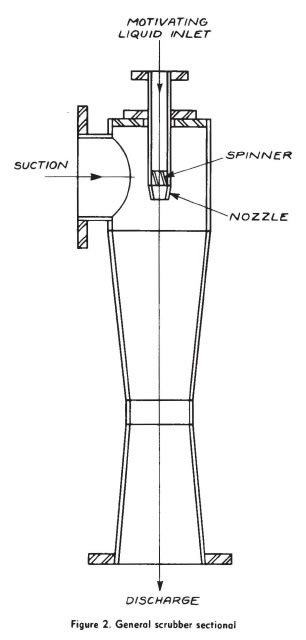
The injected liquid spray is the driving fluid which moves the contaminated gas into and through the Venturi where intimate cocurrent contact between the liquid and gas phases is achieved. The jet Venturi fume scrubber can effectively scrub out gaseous contaminants as well as solid particulates and droplets, and provide a draft if required. Contaminant transfer from the gas to the liquid phase in the scrubber, and the more easily handled liquid is separated from the “clean” gas on the downstream side of the scrubbing device.
Both liquid/gas ratios, typically expressed in U.S. gal/min/1000 ft cubed/min and liquid spray-nozzle supply pressure, normally expressed in psig, are directly related to the efficiency of the jet Venturi fume scrubber. Strictly speaking, it is the liquid spray-nozzle pressure drop, which corresponds to the degree of liquid atomization that is achieved, rather than the liquid supply pressure, that is the pertinent parameter. However, since the majority of the systems operate under atmospheric or nearly atmospheric conditions, the gauge supply pressure number also represents the spray-nozzle pressure drop.
Generally, liquid/gas ratios range from 40 to 100 gal/min/1000 ft cubed/min (5.35 to 13.37 m cubed/hr/l000 m cubed/hr, although increased ratios are not uncommon. Liquid nozzle supply pressure ranges from 15 to 120 psig (1.034 x 10 to the fifth to 8.274 x 10 to the fifth Pa gauge). In a given jet Venturi fume scrubber, performance (in terms of gas capacity, draft, as well as contaminant removal) is improved with increased liquid/gas ratio and/or liquid supply pressure.
In this particular application, it was determined that a conservative (high-side) first-stage system “A” gas capacity of 5000 m cubed/hr (2,928 ft cubed/min) was required. This corresponds to evacuation of the entire reactor system in approximately one minute. The volumetric rate entering the scrubber would, of course , be equal to the equivalent volume of the reactors when expanded through the relief valve to atmospheric pressure. The actual venting rate, even during severe upset, should be only a fraction of the design rate.
Because the bulk of the vapors relieved during a runaway would be the solvent mixture, rather than inert air or nitrogen, an extremely large scrubbing stream of water is required to quench the gases. Specifically, 228 m cubed/hr ( 1000 gal/min) of water are used to condense virtually all of the boiling solvents and to capture the highly toxic isocyanates, namely TDI, which are expected to be present in the form of liquid droplets. The liquid-supply pressure required at the jet Venturi fume scrubber liquid-spray nozzle is 2.068 x 10 to the fifth Pa gauge (30 psig). The separator tank into which the Venturi discharges has a volume of 15m cubed (3,960 U.S. gallons). The jet Venturi scrubber is a model 18 x 18, having gas suction and discharge connection sizes of 0.4572 m (18 inches ), liquid inlet size of 0.2032 m (8 inches), and an overall length of 2.49M (8 feet-2 inches).
Since system “A” is an emergency system only, it is quite practical to use a large volume of water as scrubbing liquid which would not be reused. Typically, minimization of water usage is achieved in continuously operating jet Venturi scrubber systems by maintaining a small continuous blowdown of water or water and chemical and, if required, cooling the recirculating scrubbing liquid with an in-line heat exchanger. In this situation, the cost of a feed and blowdown system, including appropriate controls, is not a practical alternative to a simple “batch” type design in which a large amount of water is used rarely, or hopefully not at all.
System “A” is activated when either the operating pressure or operating temperature in one of the reactors rises above a preset value. The jet-Venturi design requires no elaborate controls or instrumentation. With a properly designed liquid-recirculation pump, the preferred method of operation is to maintain a completely open liquid recirculating line to take advantage of the maximum pump output. The liquid-supply pump for the system-” A” scrubber is automatically activated, putting the system into operation instantaneously as the pressure-relief valve opens exhausting the contaminated gases into the exhaust-duct system and finally into the scrubber.
Since the water will primarily cool down and condense the boiled solvents, sufficient spare volume is provided in the separator tank for this condensate. A fraction of the TDI may react with the water in the first stage to produce relatively innocuous urea compounds.
The small amount of vapors not scrubbed in system “A” then exhausts to system “B”.
System “B” has a gas-handling capacity of up to 100m cubed/hr (58.57 ft cubed/min). The jet-Venturi scrubber in use is a model 33 with 0.0762 m (3 in.) suction and discharge connections, with a 0.0381 m (1 .5 in.) liquid inlet and an overall length of 0.58 m (23 in.). TDI is the primary contaminant being scrubbed in system “B” and must be removed effectively; therefore, an alcoholic alkali liquid is used as the scrubbing medium. Aqueous ethyl alcohol with 1-2 weight % potassium hydroxide, as a catalyst, reacts very quickly and completely with TDI. The scrubbing solution is recirculated from a 0.5-m cubed(132-U.S. gallons) separator tank. The solution is maintained in a reactive state at all times. Again, this stage must be operating continuously as well as being able to accommodate the discharge from system “A” during emergency conditions.
The scrubbing-liquid recirculation rate to system “B” is 1.73 m cubed/hr. (7.6 U. S. gal/min) with a liquid-supply pressure to the spray nozzle of 2.07 Pa gauge (30 psig). The system ”B” jet Venturi fume scrubber is capable of creating a 497.6 Pa (2″ w. c.) draft under “normal” continuous operating conditions with an inlet gas rate of 50 m cubed/hr (30ft /min). This is half the capacity required under emergency conditions. When operating in its continuous mode, the slight draft is sufficient to move any vapors thru the exhaust-ductwork system from the vented reactor or reactors as well as through the dormant system “A”.
At an inlet-gas rate to system “B” of 100 m cubed/hr(60 ft cubed/min) the jet Venturi fume scrubbers create very little draft. Of course, when this occurs, no draft is required to be supplied by the system “B” scrubber.
Supplying The System: The system was designed in detail after the final operating parameters, as outlined above, had been agreed upon by all parties involved. Due to the critical dimensional tolerances required for the proper construction and subsequent operation of the two jet Venturi fume scrubbers, these two items were completely manufactured m the United States by the CR Clean Air Group, LLC Petrarca, B. V. arranged for the manufacture of the separator tanks in Europe in accordance with the CR Clean Ai Group, LLC design. In addition, Petrarca B. V., in conjunction with the manufacturer’s engineers, worked with NKI with respect to the overall design of the scrubbing systems, including pumps, piping, instrumentation, etc.
The scrubbers and tanks were fabricated from mild steel. Mild steel was determined to be suitable for the noncorrosive to mildly corrosive environment faced by the scrubbers under short-term emergency conditions as well as continuous normal operation.
Results: The scrubbing system has been installed and system “B” has been operating successfully for over three years. Tests have been made to verify the effectiveness of system “B” in removing TDI emissions. Following is a description of the test and the results
Two isocyanate detectors were installed to determine the efficiency of the second-stage scrubber, system “B” The detectors were UEI Model 7000. This device photoelectrically monitors a colored stain which appears on a paper tape after exposure to TDI due to reactions with chemicals impregnated on the tape.
The detectors were connected to a dual-pen recorder, so that inlet and outlet concentrations could be measured and recorded independently and simultaneously.
The tests were conducted using vapors exhausted from a reactor to system “B”. The reactor was filled with 0.16 m cubed (42.06 U.S. gallons) TDI, nitrogen being used as the carrier gas.
The contents of the reactor were heated up to 70°C (158°F) to produce a higher concentration of isocyanate in the nitrogen.
The following data are of importance: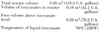 TEST #1: After several trials, the reactor was vented five times in succession from 9.99 x 10⁴ Pa gauge (14.5 psig) to atmospheric pressure, this being followed by a continuous flow of nitrogen through the reactor. The total test lasted some 15 minutes.
TEST #2: The reactor was vented five times in succession from 9.99 x 10⁴ Pa gauge (14.5 psig) to atmospheric pressure, followed by continuous flowing of nitrogen through the reactor. The test lasted some 3 minutes in total.
TEST #3: Now, the reactor was vented ten times in succession from 9.99 x 10⁴ Pa gauge (14.5 psig) to atmospheric pressure, followed by continuous flowing of nitrogen through the reactor. This test lasted some 5 minutes.
For Tests #2 and #3 the positions of the two UEI 7000 isocyanate detectors were reversed, so that the detector which in Test #1 was connected to the inlet of the system was now connected to the outlet of the system, and vice versa.
The concentrations of isocyanate at the inlet and outlet of the scrubber system were recorded as peaks on a strip-chart graph. The results are listed in the following table:
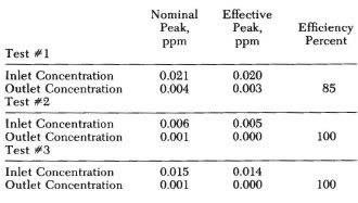 Discussion of Results: For evaluation of these results one must remember that the base line of the recorder lies at 0.001 ppm. This deviation of the zero value is caused by a slow discoloration (yellowing) of the chart paper in the air. The discoloration caused by isocyanates is blue and is clearly distinguishable.
The results of the tests described above show that the scrubber system indeed works as planned and guaranteed for elimination of isocyanate vapors. The efficiency is between 85% and 100%. Although a 100% efficiency can hardly be accepted as true, the experience of the normal everyday operation confirms that a very high efficiency of the system is a fact.
We must further remember that the scrubber is not continuously subjected to high concentrations of isocyanate. An isocyanate load occurs only when the reactors are being vented and/or while filling the drums.
Summary: The use of a two-stage jet Venturi scrubbing system is a relatively uncomplicated but effective method to handle a large hazardous-reactor runaway emission of TDI and solvent vapors when required, as well as a considerably smaller continuous hazardous emission. Continuous operation of one stage has been shown to provide high removal efficiencies of TDI. Automatic switchover to emergency operation is simple, requiring no rerouting of exhaust gases.
By: Robert J. Chrionna, The Clean Air Group, LLC and L. P. Voepel, B. V. Nederlandse Kleurstorindustrie, Amersfoort, Holland.